A is the Continual Repetition of the Cpu to Process Instructions
In order to simplify and make the concepts explained in this article more understandable, we have decided to describe an extremely simple processor for current times, so in this article you will see an explanation of what instruction cycles are in a generalized way that can be apply from the first 8-bit processors to the most complex ones available today
Contents
- Visualizing the instruction cycle
- First stage of the instruction cycle: Fetch
- Control unit
- The second stage: Decode
- Third stage: Execute
Visualizing the instruction cycle
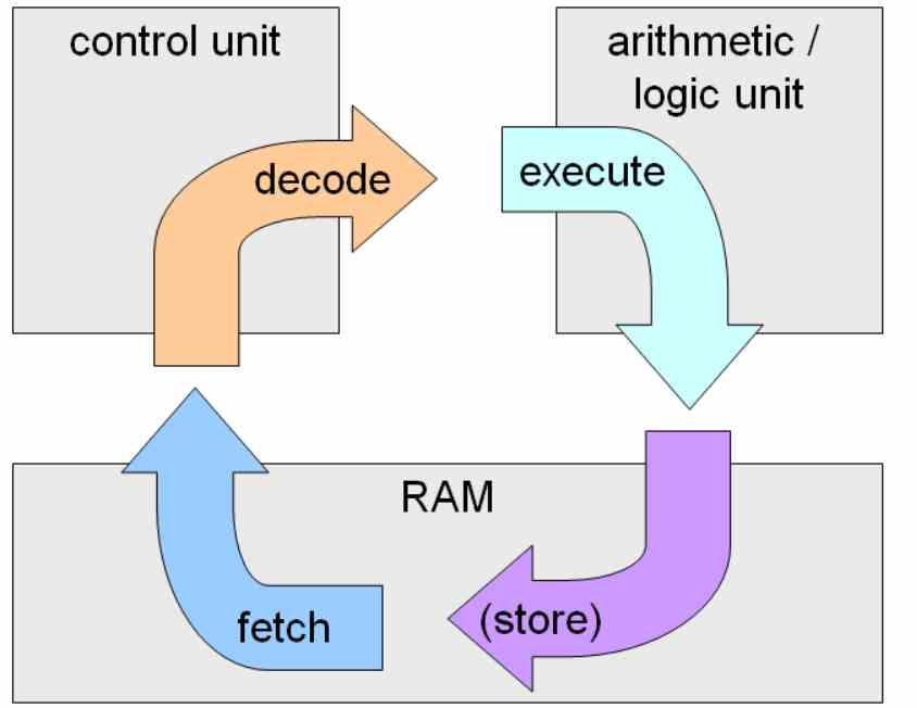
Processors are not different from a certain point of view to a combustion engine, which always carry out a continuous process of fuel explosion in different stages, whether they are 2-stroke or 4-stroke. The reason for this is that the processors work in three different stages in their simplest version, which are the following:
- Fetch or Capture: In which the instruction is captured from RAM and copied to within the processor.
- Decode or Decoding: In which the previously captured instruction is decoded and sent to the execution units
- Execute: Where the instruction is resolved and the result written in the internal registers of the processor or in a memory address of RAM
These three stages are fulfilled in every processor. There is a fourth stage, which is Write-Back, which is when the execution units write the result, but this is usually counted within the execution stage of the instruction cycle.
First stage of the instruction cycle: Fetch
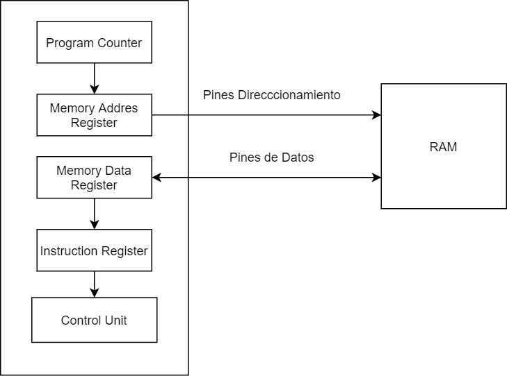
The first stage of the instruction cycle is responsible for capturing the instructions in the RAM memory assigned to the processor through a series of units and registers that are the following:
- Program Counter or Program Counter: Which points to the next memory line where the next processor instruction is located. Its value is incremented by 1 each time a complete instruction cycle is completed or when a jump instruction changes the value of the program counter.
- Memory Address Register: The MAR copies the content of the PC and sends it to the RAM through the addressing pins of the CPU, which are wired with the addressing pins of the RAM itself.
- Memory Data Register or memory data register : In the event that the CPU has to perform a memory reading, what the MDR does is copy the content of that memory address to an internal register of the CPU, which is a temporary pass register before its content is copied to the Instruction Register. The MDR, unlike the MAR, is connected to the data pins of the RAM and not to the addressing pins and in the case of a write instruction the content of what you want to write in the RAM is also written in the MDR
- Instruction Register: The final part of the fetch stage is the writing of the instruction in the instruction register, from which the processor control unit will copy its content for the second stage of the instruction cycle.
These 4 sub-stages occur in all processors whatever their utility, architecture and binary compatibility or what we call ISA.
Control unit
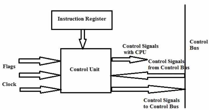
The control unit is the most complex part that exists in a processor and its tasks are as follows:
- They are in charge of coordinating the movement and the order in which of the data that moves inside and outside the processor, as well as the different subunits that are in charge of it.
- In general, it is considered that the units of the capture stage or Fetch are part of the hardware that we call the control unit and this hardware is also called the Front-End of a processor.
- It interprets the instructions and sends them to the different execution units to which it is connected.
- It is communicated to the different ALUs and execution units of the processor that act
- It is responsible for capturing and decoding the instructions, but also for writing the results in the registers, caches or in the corresponding address of the RAM.

What the control unit does is decode the instructions and it does this because each instruction is actually a kind of sentence where the verb goes first and then the direct object or object on which the action is done. The subject ends up being eliminated in this internal language of computers by the fact that it is understood that it is the computer itself that executes it, so each number of bits is a sentence where the first 1 and 0 correspond to the action and the ones that come next is the data or the location of the data to be manipulated.
The second stage: Decode
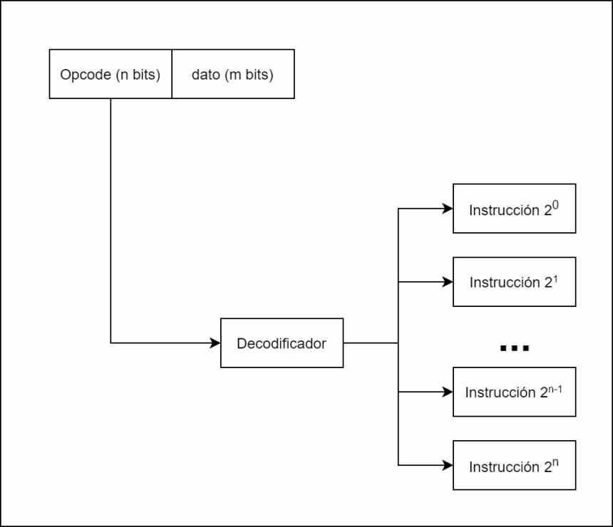
There are different types of instructions and not all of them do the same, so depending on the type of instruction we need to know what execution units are going to be sent to and the most classic way of doing it is through what we call a decoder, which takes each instruction, divides it internally according to the opcode or instruction and the data or memory address where it is located.
For example in the diagram above we have the diagram of a processor with only 8 instructions, which can be encoded in only 3 bits. Each one of the instructions, once decoded, is sent to the different execution units that will resolve them.
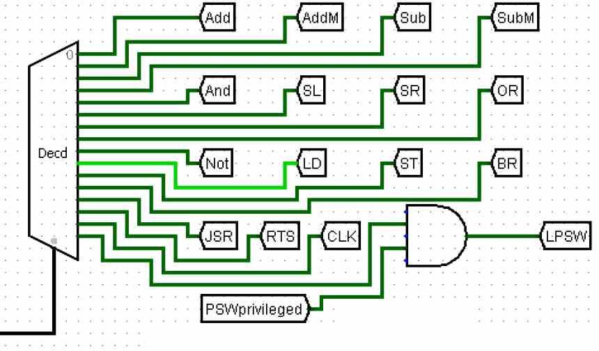
This instruction cycle is the most complex of all and the one that defines the type of architecture. Depending on whether we have a reduced or complex set of instructions, this will affect the nature of the control unit, depending on the format of the instruction or how many are processed at the same time the decoding phase and therefore the control unit will have a different nature. other.
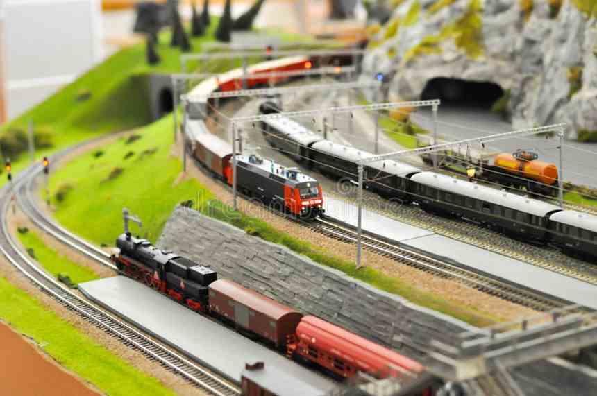
The easiest way to visualize what happens is to think of the instructions as trains circulating through a complex railway network and the control unit directing them to a terminal station, which is the execution unit that will be in charge of solving the instruction.
Third stage: Execute
The last stage is the execution of the instructions, in this stage the instructions are resolved, but not all types of instruction are resolved in the same way, since the way to use the hardware will depend on the function of each one of them. them, in general we have four types of instructions:
- Bit movement instructions: In which the order of the bits that contain the data is manipulated.
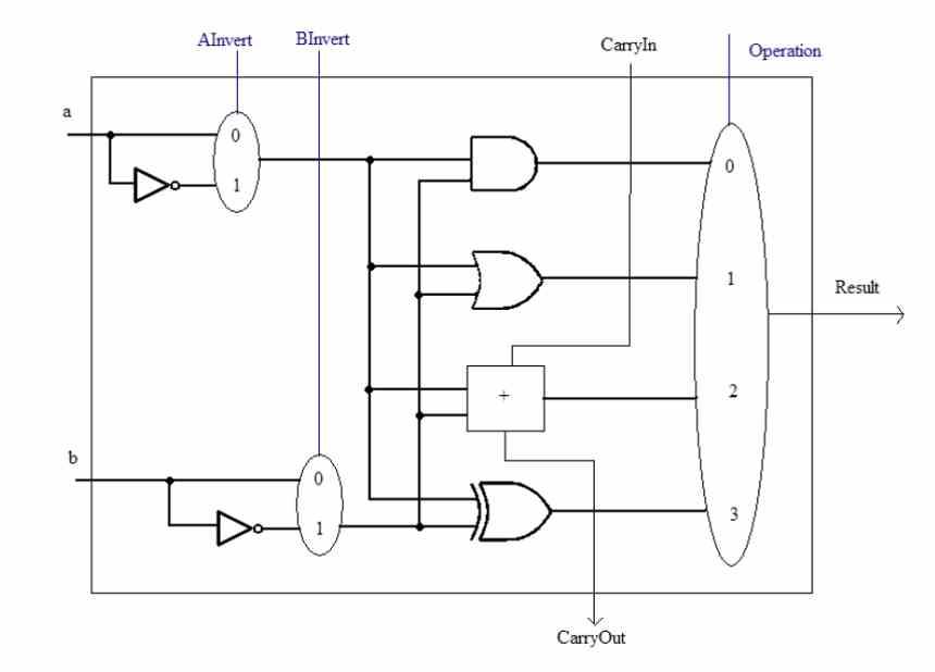
- Arithmetic instructions: Where mathematical and logical operations are carried out, these are solved in the so-called ALUs or arithmetic-logical units
- Jump instructions: In which the next value of the program counter is changed, which allows the code to be used recursively.
- Instructions to memory: They are with which the processor reads and writes information from the system memory.
The other point is the instruction formats, since an instruction can be applied to a data, scalar or several data at the same time, which we know as SIMD. To finish and depending on the data format, there are different types of ALUs for the execution of arithmetic instructions, for example we have integer and floating point units as differentiated units today.
Once the instruction has been completed, the result is written to a specific memory address and the next one is executed. Some instructions do not manipulate memory values but rather certain registers. Thus, the program counter register is modified by the jump instructions, if we want to read or write data then the MAR and MDR registers are manipulated.
Source: https://itigic.com/instruction-cycle-in-cpu-how-fetch-decode-and-execute-work/
0 Response to "A is the Continual Repetition of the Cpu to Process Instructions"
Post a Comment